Electric Gear Roll
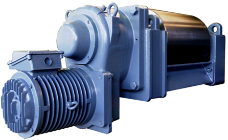
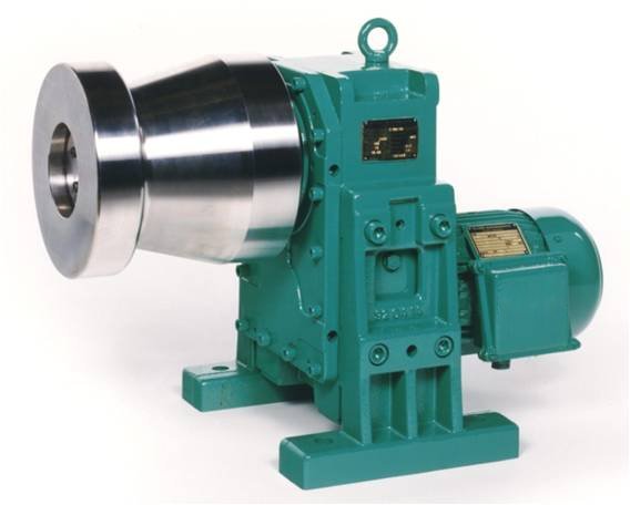
From the company KLOSE or the company aggregates built by gemota are units consisting of several components. The structure of a roller table is a stable substructure on which a roller is guided precisely aligned in two pillow block bearings (drive side AS and operating side BS). The transmission + motor already presented is then installed on the drive side. This compilation also makes it clear that the load on the pillow block AS due to the weight increases as the length of the drive increases.
If a system malfunctions, it is often important to replace the electric gear roller as quickly as possible. For this purpose, the pedestal bearings are additionally connected with one or two traverses. The pillow block bearings are fixed laterally in the roller table in quick-change devices. With eyebolts or slings it can be removed quickly using a crane.
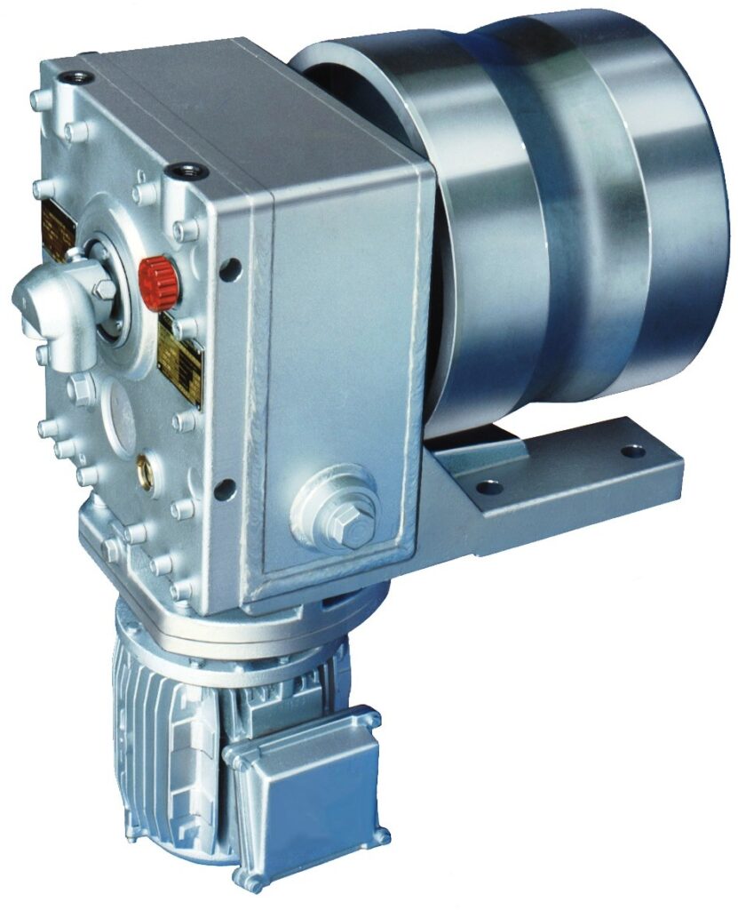
The following illustrations show two versions of these aggregates. You can see a difference in the length of the rolls. But both units are the same in terms of the structure described above.
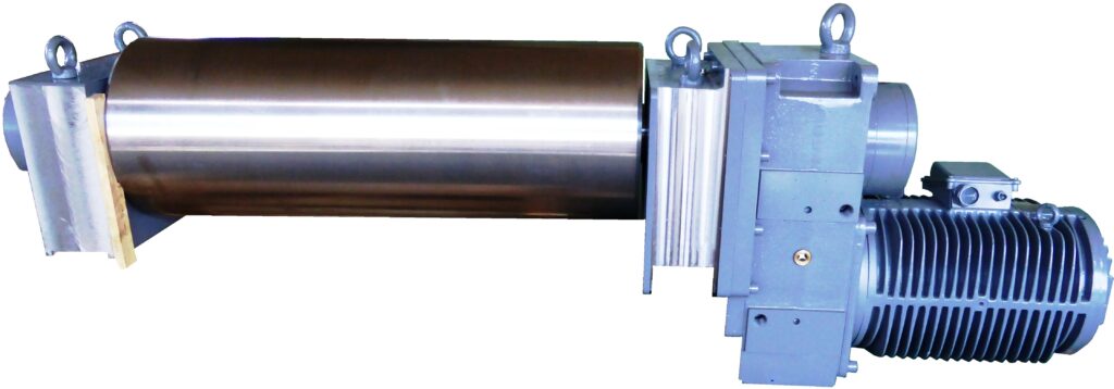
Other versions of the electric geared castor
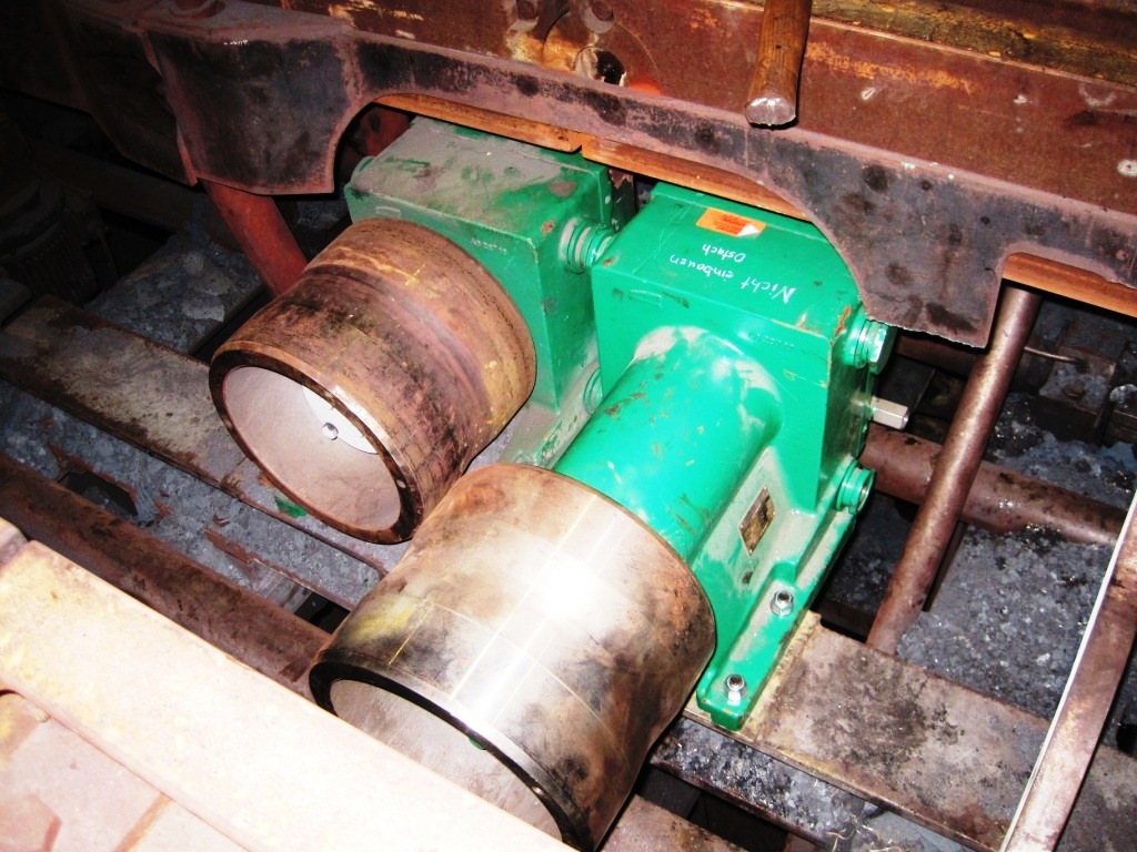
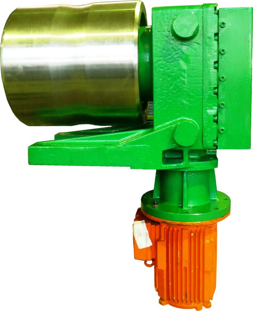
If, for example, in continuous casting plants, the round steel or billets are transported via a very short roller, then the pillow block bearing on the operator side can even be omitted. In these designs, the gearbox becomes the pillow block bearing for the entire roller table unit with a very solid housing and a very stable base. On one side, the housing and base absorb the forces from the motor. But the housing and base also support the roll on which the material lies. The roll alone for large continuous casting systems weighs over 250kg and the billet lying on it weighs another 1 ton per meter. This material transport is subject to large shocks, which in turn requires an even more stable construction. The basic design of this electric gear reel is a reinforced housing and a strong base with four screw points. The screw points often have fire sleeves to avoid having to unscrew the screws for disassembly. To make the change quicker, the screw is burned off and the entire unit is simply lifted off by a crane.
The following pictures show different versions of an electric gear roller for different stick sizes.
Some versions also have a water-cooled housing and a water-cooled gear shaft (with a rotary union at the rear) to protect against heat radiation. The motor is suspended downwards (out of the thermal radiation from the stick) via a bevel gear stage. Two-stage gears with a gear ratio of up to 1:20 and three-stage gears with a gear ratio of up to 1:60 can be manufactured.
